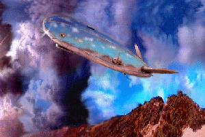
EyeBot

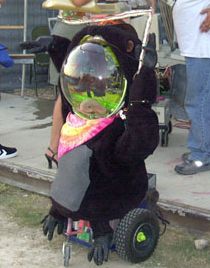
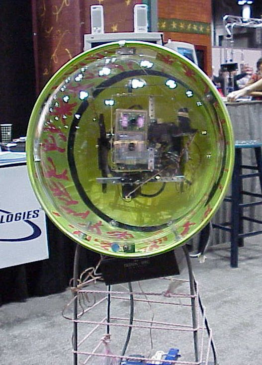
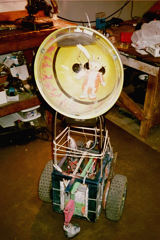
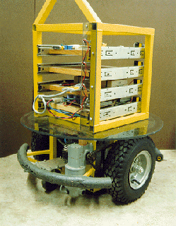
Tom Davidson & Sonia Santana are the forces behind, EyeBot, a mobile platform telepresence robot based on the Mobile Platform Mechanics. The control is a very basic R/C 4-channel using two 12V electronic speed controllers, and 2 R/C car servos.

The “Super-Rooster” speed controllers are capable of 128-levels of proportional control in forward and reverse and can handle up to 150 Amps at 12 Volts.

The servos are used in a gimbal which carries two Supercircuits microcameras, one an infrared monochrome camera and the other a high-resolution color camera. The video and audio signals are relayed by a X-10 2.4 GHz video transmitter-receiver pair.

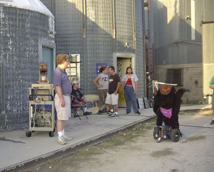
EyeBot has made numerous appearances at The Robot Group events. The kids love EyeBot because it is approachable and appears to dance with them.

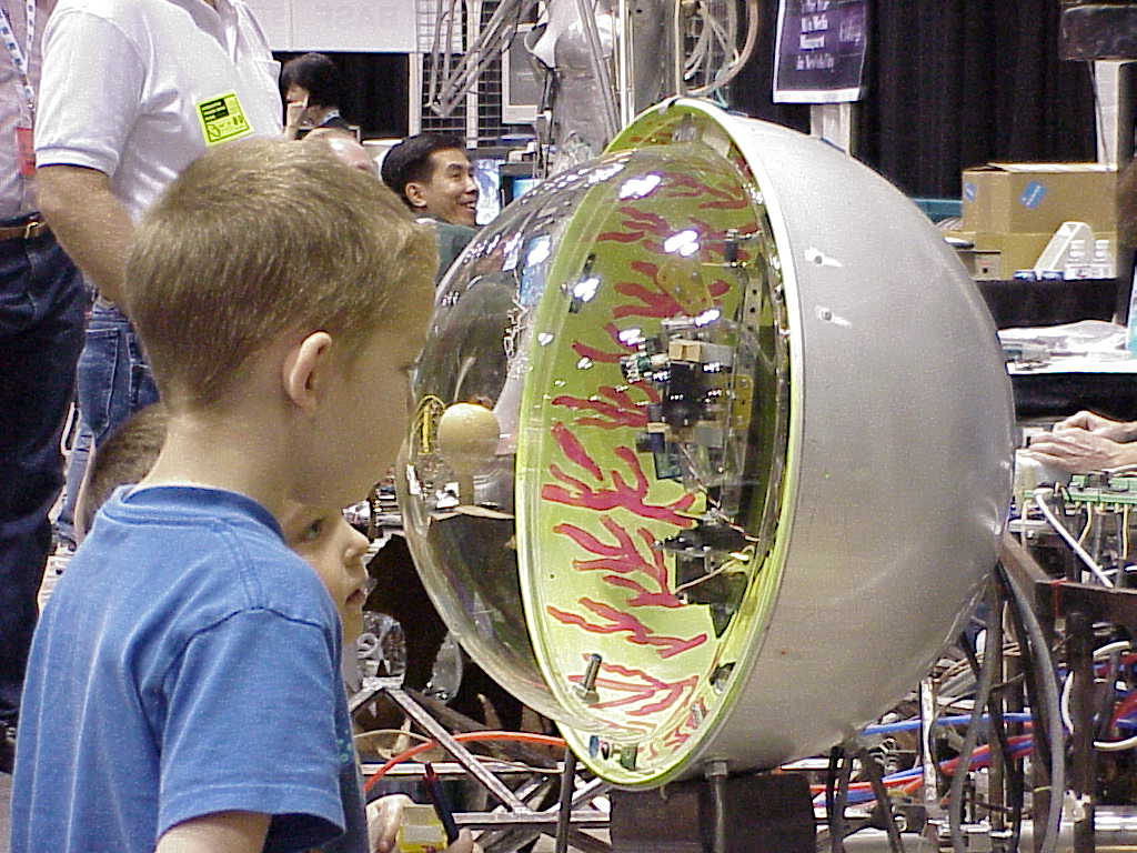
Youngsters admiring EyeBot @ SXSW 2000

In addition, EyeBot appeared in the 2001 Robert Rodriguez film, Spy Kids.

Mobile Robotic Platform

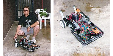
Eric Lundquist‘s Mobile Robotic Platform was an experimental built-from-scratch design with several unique features. Its behavior was very moth-like in that it chased the brightest light that it could detect. Obstacles were detected and avoided with feeler wires on 3 sides.

The brains of the Mobile Robotic Platform were a Parallax BASIC Stamp I providing 8 I/O lines and programming in a dialect of BASIC. Eric added a Stamp Extender that provided an additional 16 I/O lines.

The BASIC Stamp drove the motor and direction relays, the LEDs, and the Piezo buzzer. It also monitored the status of bumpers and polled light levels from its 3 photocell “eyes”.

The base was painted pine shelving material. Not only was this low cost, it did not require any specialized tools to work aside from a circular saw. It also made it exceptionally easy to mount, fasten, and rearrange things.

Eric’s ultimate goal with this project was to add several more BASIC Stamp controllers to make a distributed parallel architecture. This would have allowed more complex behavioral responses and interactions with the environment.

Negative Head

[Editor’s note : This information was extracted from an entry in an old version of The Robot Group web site archived by the Wayback Machine on 1996-12-04. Sorry, no photographs have emerged to-date.]

Negative Head is another face character for the planned robot theatre performance being directed by Brooks Coleman. The Negative Head is made from street lamp parts and servos. It creates face movements by overlaying transparent patterns to grids.

Arthur … The Door Butler

Leon Hubby proposed this project.

Description

“Arthur … The Door Butler will resemble a very normal door. As you approach, you will see a door mounted in a partial wall with a very standard motion detector mounted at the top and a porch light to the side. A welcome mat will greet the visitors.”

Operation

“As the visitors approach, the motion detector will turn on the porch light and enable the door to greet the individuals. When the visitors step on the welcome mat, Arthur will open and then close the door for them. First, a compartment on the side of the door will open, a robotic arm will unfold, raise itself, and position to grasp the door knob. Arthur will then grab the door knob, rotate it, and open the door. A mat on the other side of the door will signal Arthur that the individual has passed through. The arm will then close the door, release its grip, and refold itself up closing its access door. “

Artistic and Technological Content

“Art, as they say, is in the eye of the beholder. From my perspective the door represents a sculpture in motion. The image of an automatic door does not invoke much artistic impression. A door that lends a hand and opens itself, however, tends to be a bit more intriguing, if not novel. The technological content is centered around making a light-weight yet strong arm and gripper. This project will explore the use of different sensors to detect individuals, the door knob, etc. Differing techniques will be used to center the gripper on the door knob, close around the knob, and rotate to open it. This project will also explore the control aspects using the HC11E9. Special efforts and attention will be placed on the construction of the arm in order to build a light-weight, strong arm. The arm will be constructed of either PVC pipe or Styrofoam coated with epoxy fiberglass.”

RoboVision

RoboVision was a quick virtual reality (VR) project by Tom Davidson and Sonia Santana. The aim of the project was to provide attendees at RoboFest 7 a feel for what a robot’s vision might be like.

The project’s components were two VictorMaxx Stuntmaster VR headsets which had their video inputs wired to Supercircuits microcameras. The Stuntmaster had a single camera screen. The microvideo camera was mounted on the outside of the head gear with the battery power unit worn as a belt pack. An on/off timer switch was been wired to the helmet to allow more participants equal access. The entire head unit was covered with a cardboard mask design similar to that of the Megabot Army for a cool robot head appearance.

There was ample room in the head gear to allow for downward vision so that the person wearing the helmet could walk around and avoid tripping over stuff. The camera images that were projected into the headset screen were feeds from various mobile robots such as Commander Salamander and Mobile Platform and Dweebvision.

Mobile Platform

Editor’s note : The contents of this page were extracted an archived entry found on the Internet Archive’s Wayback Machine. The page, originally on Carlos Puchol’s web space at The University of Texas – Austin, was archived on 1996-12-31.

Introduction to the Mobile Platform

The mobile platform project is designed to provide ground-based mobility to experimental sensor and control systems, allowing them to traverse level surfaces such as building floors, and possibly streets and backyards. Think of it as a Hero robot on steroids.

Mobile Platform Mechanical System

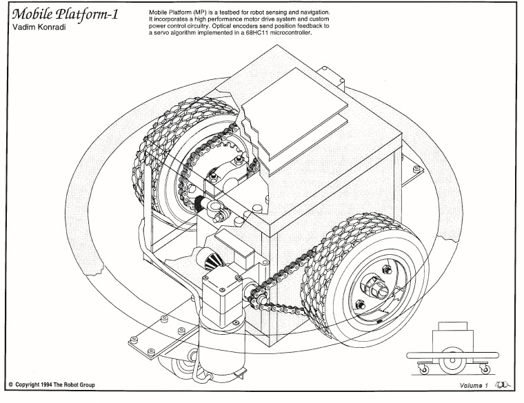
The mobile platform is supported by two main drive wheels, with stability augmented by fore and aft caster wheels. Depending on distribution of weight in the platform and payload, it may be self-righting through balancing about the main wheel axis. Possible caster wheel heights are bounded on the low end by the need to negotiate unlevel surfaces and, on the high end, by the need to maintain the platform more or less level during dynamic maneuvers. Caster wheel mounting heights and possibilities for controllable height adjustments need to be investigated.


The vehicle platform is designed to fit within a 2-foot circle so it can navigate doorways and turn within its width. Currently equipped main wheels are 11.5 inches high. The platform structure is made up of 1-inch square steel tubing in a box structure. Vertical hard clearance when level is 2 inches. The top of the box structure is 12 inches above the floor. In general, platform structure below the 12 inch height is intended to be dedicated to platform mechanicals, and passenger equipment will mount to the top surface. The upper surface consists of a perimeter structure of 1-inch square tube, 10 inches wide by 11 inches fore-aft. We will equip it with mounting holes or tabs, or studs, or tape things on top with duct tape.

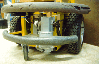
Platform main wheels are driven from wheelchair motors via #35 roller chain. Based on preliminary observations, motive force of the system will be limited primarily by tire friction. Based on measured motor torque of _____, and a _____ : _____ reduction ratio, the horizontal stall force will be _____. Thus a heavily-loaded platform will be able to push over or drive through certain static objects. Some motor current sensing or other safety mechanisms may be appropriate. A perimeter bumper system with contact switches will likely be installed eventually.

Mobile Platform Electrical / Electronic System

The mobile platform electronics are designed for control via a Motorola 68HC11 microcontroller Evaluation Board (EVB). The EVB receives movement commands from a higher authority and performs the necessary control functions to drive the platform motors. The EVB has been used as a basis because it is a handy development system. Eventually the motor drive circuit board will probably have an on-board HC11.

Control is currently passed to the EVB via a standard serial port for testing in conjunction with a data terminal. Eventually control will be migrated to the HC11 Serial Communications Interface (SCI) for interprocessor communication.

The motor drive power electronics reside on a circuit board with the same dimensions as the EVB and similarly placed 60-pin connector. It is capable of being mounted, with a suitable connector, as a daughter board on top of the EVB. Logic and motor drive circuitry are separate, with optical coupling of control and status signals in both directions. Motors are controlled via enable and direction signals. The enable is pulse width modulated (PWM) to control motor speed. In addition to the individual motor enables, a global driver enable allows shutdown of the entire power output stage. An overcurrent sense signal is sent back from the motor driver circuit to the HC11.

Each motor driver consists of four MOSFET transistors in an H-bridge configuration, controlled by a _____ IC. The most recent circuit version is equipped with IRF540 MOSFETS, giving it current capability of 27 A continuous, 108 A peak. This appears to be a reasonable transistor size for efficient operation at anticipated motor power levels. MOSFETS with higher current ratings may be substituted as required. The motor driver circuit is currently programmed for overcurrent limit of approximately 20 A, which may be modified by changing the current sense shunt.

Optical encoders on the motor output shafts are used to feed back motor position to the HC11. Each encoder consists of a pair of optical interrupters and an encoder wheel. The encoder sensors use a Schmitt trigger buffer to control encoder hysteresis. Optical encoder outputs are fed to the HC11 via connectors on the motor driver board. Connectors are 4-pin .100 type.

The motor driver circuit board is designed to operate with input voltage in the 5V-30V range. Full turn-on saturation of the MOSFETS is not guaranteed below 10V, so operation is not recommended in this range with a large motor load. Power connectors on the power board are Molex .093 series 2-pin connectors, connecting to male connectors on batteries and female connectors on motors. The motor drive circuit is fused with a standard automotive type fuse. The fuse should protect against melted wires and boiling batteries in the event of an output short. Current limiting by the transistor driver IC should protect the MOSFETs to some degree. This will no doubt be determined experimentally at some time.

There is an undesirable and potentially exciting design defect on the current version of the power board, resulting in runaway full-speed drive of the motors when power is removed from the control logic. This will be corrected on future versions. For the moment, it is necessary to ensure that logic power is applied prior to application of motor drive voltage, and motor drive voltage disconnected prior to disconnection of logic power.

Control Algorithm

General

The HC11 program which controls platform motion is mainly interrupt-driven. Encoder transitions are serviced as they occur. A real-time counter schedules updates of the trajectory generator and control loop. PWM transitions are controlled by HC11 internal timers, which are reset at the PWM frequency. Implementations of these functions are more or less similar to HC11 databook examples.

Movement Command Set

Platform movement is directed through commands to the HC11 via the serial port. The following is a summary of currently implemented commands :

  • Calibrate – sets setpoint position equal to current position (overrides move in progress)
  • Translate (direction,magnitude) – forward or reverse increment to current setpoint position
  • Rotate (direction, magnitude) – rotates right or left about platform centerline
  • Velocity (direction, magnitude) – gives platform velocity in specified direction
  • Radius (direction, length) – specifies curve radius in conjunction with velocity commands
  • Motor (direction, magnitude) – allows independent increments topology motor setpoints
  • Control (various parameters) – allows resetting of control equation constants and limit values

“Magnitude”, a parameter in many commands above, is expressed in terms of encoder counts, and the relation to physical movement distance is a function of encoder resolution, gear ratio, and wheel size. Encoders should eventually be sized such that some whole number relation exists between counts and distance in standard units of measure. Radius is specified in increments of half the vehicle track.

Commands as currently implemented return prompt strings to the data terminal. Such information will be omitted for interprocessor control via the SPI.

Wheel Position Settings and Trajectory Generation

Each wheel has an associated destination position counter. The count values are modified through addition and subtraction of increments for instantaneous movements. Velocity commands cause the velocity value to be added to the wheel counts at the trajectory generation timestep interval. When a non-straight path is directed via the Radius command, the destination counts are incremented differently to achieve the desired radius. Operation at large radii is not smooth; the algorithm may be modified someday.

Translation, rotation, and velocity commands may be overlaid with predictable, though not always intuitive, results. In general, translation and rotation commands are intended to be applied disjointly, and separately from velocity commands. Velocity and radius commands are intended to be used together in a smooth manner. All commands take effect immediately but translations and rotations modify endpoint positions, whereas velocity and radius commands modify the incremental setting of new endpoints.

Eventual additions to the command set may include profiled moves, consisting of acceleration, maintained velocity, and deceleration. Other means of limiting acceleration and jerk forces via programmable limits are possible. Another feature, primarily applicable to translation and rotation commands, would be the ability to queue commands, i.e. move forward 5, turn left 2, move forward 8. Eventually the command set will probably need to be divided into two or more distinct modes of operation.

Encoder Sensing and Actual Position Determination

Optical encoders send two digital signals in quadrature to HC11 inputs. Transitions on one signal are recognized, at which point an interrupt routine reads the other signal and determines direction of encoder motion. New position is compared with previous position for the possibility of encoder error which is not really handled correctly right now anyway. Then the wheel position count is incremented or decremented as appropriate.

Generation of Motor Force Function

Voltage applied to each motor is determined via a comparison between destination position and actual position. If there is any difference, the control algorithm exerts force through the motor to drive the error to zero. The position control is implemented in a proportional-integral-derivative (PID) loop, with command-settable gain values for each term. The motor PWM duty cycle is also subject to a command-settable limit. The result of the control calculation is a duty cycle, which is used by the PWM logic to generate a PWM output from the HC11 for the motor driver circuit.

Error / Failure / Problem Resolution

Some work needs to be done in recognizing problems with platform motion such as bumping into objects, motor overcurrent, encoder / drivetrain / wheel slip, etc., and acting on these problems accordingly. The control algorithm will need to shut down activities which are causing problems and report back to its higher authority.

Balancing Act

Since the platform has two wheels, fairly responsive motors, and a dedicated controller, it may be possible to perform active balancing of top-heavy loads without relying on the caster wheels. This is actually not that farfetched, but would require some attitude-sensing hardware and algorithm development. It would also be totally cool.

Mobile Platform no. 2
Glenn Currie’s design for the Mobile Platform (from TRG Coloring Book by Norm Annal 1994).

Hexwalker

Hexwalker was built from a kit produced by M & T Systems in Huntington Beach California.

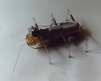
The body is made of perforated circuit board material. It has three R/C type servos driving the legs and a Basic Stamp for a brain. Antennae on the front sense obstacles and, after a few steps in reverse, send the creature off in another direction. The method used to obtain the alternating triangle gait is ingenious in its simplicity in that it can do with three servos what usually takes at least three per leg.

Don Colbath, who built this kit reports, “I was not totally happy with the construction methods and materials used and decided to build my own body and legs to attach to the existing servos and brain. This has not turned out to be as easy as I imagined and my “Hexwalker Mark II” is still undergoing refinements. My ultimate goal is to enlarge my version to about coffee table size then later to a size that a person could take a ride on. Stay tuned for future announcements.”

The background material for this page is derived from an archived page on the Internet Archive Wayback Machine. Some links may have been added, removed, or updated.

Cartwheels Gizmo Box

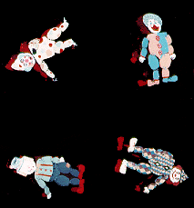
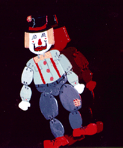
Susan Alexander‘s Cartwheels Gizmo Box is a collection of characters mounted on rotating shafts. As they turn, they appear like circus acrobatic clowns performing for an audience.

Detail of Cartwheels Gizmo Box by Susan Alexander

Susan has also designed another performance piece called Nervous People which are characters on radio-controlled platforms that move around stage briefly and then “spaz out.”

The Cartwheels Gizmo Box and Nervous People were exhibited at RoboFest 7.

These pieces are part of a series of theatrical robots and performance art being designed for stage performance. Brooks Coleman is directing the robot theatre movement.

Commander Salamander – May 1996 update

Editor’s note : This information is for historical purposes only. I have done what I can to update links found on this page (current as of April 2020) but 25 year-old e-mail addresses …. Really?

The following is a first draft of limited distribution, offered for comment. In further versions numerical indexing will be added and the document will be split into linked web pages. Thanks for your input.

+==oOo===+

High Performance Micro-Blimp (HPMB) Design Notes and Draft Narrative Specification

+==oOo===+

Original April, '96 post to LTA builders list -

Members of The Robot Group of Austin, Texas are building a video telepresence micro blimp capable of outdoor operation in a moderate breeze.

The aircraft will start with short "over the horizon" video/control communications range, later adding GPS and other micro avionics to the payload.

We have strong record in indoor radio control/robotic blimps and are seeking advisors and collaborators for the outdoor work.

The current spec. calls for an 18 foot blimp, with about four pounds of elective payload, capable of cruise at 12 knots or more.

One goal is to incorporate a balloonet/water ballast system to enable "high" altitude work. Another goal is to incorporate solar cells to extend missions. These are open projects to jump on.

Anyone who wants to mirror this project with their own construction and share technical resources is welcome. Contact david@robotgroup.org .

+==oOo===+

Honing the configuration -

Many folks' design/build experience, research, and flying experience went into the working concept for the HPMB. Several promising configurations and related design ideas were competitively assessed (by scoring matrix) for potential speed, maneuverability, reliability, and simplicity of construction.

A baseline for review was the classic airship design which is pendulum stable with nonvectored bilateral thrusters. Two other candidate designs incorporated vectored thrust; one was a typical twin vectored thrust design with rudder and elevator. Another was a futuristic neutrally balanced concept with tri-radially mounted vectored thrusters and no control surfaces.

The top dog, so far, is a Vee-Tailed Twin In-line Thruster design which scores high in every functional category. Its fast, agile, robust, and simple.

The dashing vee tail is an update on classical blimp tail design that reduces part count by a third, plus a surprise; a quality microblimp's vee-tail can be quickly adapted from off the shelf RC glider wings. Well known vee-tails include the Stealth Fighter and classic vee-tail Bonanza civil aircraft.

The In-line twin propulsion units, mounted just aft of center, provide as much balanced power as the blimp can carry. The advantages of this mounting approach, as popularized in the Lear Jet and DC-9, apply to blimps. In this case visualize a fat wingless vee tailed Lear Jet. This picture also resembles NASA's early lifting bodies leading to the space shuttle design. Twin electric propulsion offers vigorous yaw inputs allowing the vee-tail to be flattened in favor of pitch control. The degree of flattening is balanced against the urgent need for rudder steering in the case of a single propulsion unit failure.

+==oOo===+

Control Particulars -

Following common airship practice, this blimp will fly slightly heavy (~200-1000 grams) balanced and trimmed like a conventional (in this case semi-acrobatic) aircraft. This allows the aircraft to slowly glide down in the event of a propulsion loss, still controllable by the vee-tail. In the event of total control failure a heavy blimp comes down in due time, without sailing off to the next state.

Although the prop units are balance mounted in-line close to the 
envelope's (horizontal) center of drag (and mass), the tail's drag causes the design to pitch up a bit when power is applied and the tail surfaces are centered. Trimming the tail down levels flight and some lift is scavenged, as in conventional aircraft. To balance pitch up maneuvering advantage, the pitch down position of the vee tail lightly interacts with prop wash, due to placement of prop unit and vee-tail.

To promote easy flying and allow emergency glide down, the design has a small amount of pendulum stability, balanced against a capability to loop and roll. In slightly heavy flight the vee-tail provides further roll stability due to its dihedral. Pendulum stability, general balance, propulsion and control surface placement will all be field tuned in test phases.

Loss of any one, two, or even three of the control surfaces or propulsion units results in proportional rather than total loss of control. A single tail foil allows feeble steering in glide mode and a single motor allows a curly cue course by timed throttle application.

The flattened vee-tail imposes a coordinated roll/pitch turn technique much like the rudderless elevon design of the Flying Sphere prototype. Differential control of the propulsion units allows aggressive yaw turns. Modern RC gear allows for mixing and tuning standard pilot inputs to make unusual configurations intuitive to fly. A note on RC glider wing reuse for vee-tails- ...existing tab ailerons suffice for control at high speeds, but for close slow maneuvering rotating the entire wing is more effective. Ailerons can be frozen in place, used as trim tabs, or mechanically slaved to overall wing rotation to reduce stall.

+==oOo===+

Communications Architecture -

The big issue here is whether or how to multiplex various high and low bandwidth data streams.

Some assumptions can be made -

-Use of RC control frequencies and protocols
-High Bandwidth Video/audio and sensor telemetry.
-Emergency Locator Beacon - a high intensity pulse useful for orienting narrow angle antennas and locating the blimp in case of a total mission failure.
-Antenna Garden - A combination of highly directional and omnidirectional switchable antennas is proposed.

===included comment from Mark C. Otto===

I have recently designed a telemetry system for use on my R/C airplanes that uses a 68HC11 and SuperCircuits ATV transmitter. The audio channel is driven by a modem chip off the HC11's serial port so I get full motion video and 1200 baud data on the audio. A modem on the audio output of the TV receiver feeds my HP palmtop with the data at RS232 levels and the palmtop stores it on flash disk. My only regret is that I didn't go with PC
 electronics for my transmitter - the lack of a sync pulse stretcher on the SuperCircuits transmitter prevents sufficient sync signal integrity to drive a VCR from the recovered video.

+==oOo===+

Avionics Suite -

GPS - Provides superior positioning info for "over the horizon" work. Can be integrated to GIS, etc.
Flux Gate Compass - Backs up GPS and provides pointing info if blimp is crabbing or yawing in place.
Two axis inclinometer - Provides attitude info in aerobatics.
Thermistor - temperature reading.

+==oOo===+

MicroVideo Components -

Current cam of choice is the PC-17 Color Microvideo Camera available thru Supercircuits. Its a 2.5 ounce, 450 line, 2"cube.

Supercircuits also offers a transmitter suitable for initial flights, the 915 MHz ATV-900 (is this the model that Otto says suffers from the lack of a sync pulse stretcher?).


+==oOo===+

Altitude Control -

As a rough goal, the design's lifting volume with proper altitude control gear should allow operation in excess of 3000 meters (stretched envelope if needed). 

Balloonet system - Keeps blimp envelope taut at lower altitudes and enables climbing without venting helium. Sub issues: a) maintaining a constant relative pressure in the envelope. A photo or micro switch tensiometer mounted on the envelope could sense flaccidity and trigger air pump. and b) selecting a lightweight air pump to pressurize the balloonet. In one approach a ram air inlet may assist a fan pump. In another scheme a small piston pump or motorized "campers air mattress" pump provides the pressure. c) Size of balloonet up to about a third of total gas volume.

Drop Ballast System - Allows blimp to lighten for maneuvering or to balance helium loss, rain/ice/payload pickup. Plain water entails freeze risk. Other options include powder or mealy media or antifreeze liquids.

Frost proofing - Low temperatures could affect electronics and embrittle materials.

+==oOo===+

Propulsion -

Two Graupner 400 motors with Olympus 2.3/1 reduction gears and between 8
and 12 inch props, size subject to tuning are being used. Such components are being specified with the help of electric airplane racing guru, George Parks and Wolf of American Angler and RC Hobby of Austin. A reduction gear and large prop operate more efficiently at low speeds and high altitudes than a small prop with no reduction gear.

Positioning - The small new human carrying Hornet blimp shares inline positioning of propulsion units.

Solar Power - 2-3 sq. meters of solar film or cells could generate nearly 100 watts of power for endurance missions. Amorphous solar films in on-hand catalogs are rather heavy for their power density. Crystalline cells are fragile, expensive, and laborious to install. Better solutions are sought.

===include message excerpt from David Beck===

Perhaps there is a way that the shape of the blimp could be adapted to
focus the sun on an array in the center of the blimp. That is, perhaps the
part facing up would be clear, and the lower part would be reflective. In the center of your tube, you could suspend an array at the focus point. This would keep the array weight down, yet still generate lots of power. 
Also it would protect the array, and with the money saved on buying lots of 
cells, you could buy a few more efficient cells. You'd generate a lot of heat at that point, so you don't want to collect too much sun, but on the
other hand, the heat generated could be used to generate additional lift - so maybe you'd want a series of tubes, and make a structure kind of like an 
inflatable mat.

===end included message===

Comment - The idea of a suspended solar array under a transparent envelope window may allow for optimal tilting to solar incidence independent of the airship's roll axis. The reflective trough idea is appealing as a means of minimizing cell count. Suspending a reflective sheet in the bag would result in a near optimal catenary shape. Unfortunately the lower refractive index of lifting gas means it can't be used as a focusing lens in a convex profile.

Batteries - The latest mainstream battery technology affordable by the project will be utilized, although Ni-cads are operationally acceptable for some missions.

+==oOo===+

Envelope and Hardpoints -

A big issue is using the Mylar gas bag as the primary envelope vs. as a liner for a fabric outer skin. At this point a naked Mylar bag with tape reinforcement will be used and later upgraded as it proves inadequate. This approach will save weight, cost, and complexity in trade off with durability.

Hardpoints are rigid foam structures supporting motors, tail foils, electronics, and batteries. Stress relieving tapered stringers radiate from the hard points and attach to "crow foot" reinforced anchor points on the envelope.

+==oOo===+

Vee-Tail Construction Note -

While slight deflections of small control surface areas suffice for cruising speed maneuvers, large areas and aggressive deflections are needed for good slow speed agility. A large area/deflection approach requires special care in designing large, strong, and light articulated mountings. An oversized elevon mounted on a tapered strake is the elected layout to make these trade-offs.


+==oOo===+

Rain Proofing -

Operation in wet weather adds weight and threatens electronics.

Electronics bays are to be modestly weather proofed similarly to autos using gravity gutters and gaskets while maintaining ease of access. Loops and rolls in rain are proscribed. Drop ballast should offset modest rain/snow/ice loads. Outer envelope material should be hydrophobic (like Scotch Guard), if not waterproof, without adding much weight from fabric treatment.

Electronics and other sensitive components are to be housed in insulated enclosures. Electronic waste heat may suffice to inhibit condensation. Silica packs could help. Ram air venting might be useful if the electronic bays are too well insulated for hot weather operation.

+==oOo===+

Test Flights / Mission Profiles -

Benchmarking - Speed, climb, lift, endurance, etc. would be established in early flights.
Cross Country - Following prevailing winds and conserving propulsion for course adjustment and landing.
High Altitude - Stripping all excess payload, the high altitude capability of the design will be tested.
Sample Pickup - Touch down on (calm) water to acquire samples for biological and chemical analysis.
Exploration in close environments - Urban and rural canyons, building interiors and other crowded locations put a premium on agility.
Station Keeping - Maintaining a constant position for as long as resources allow. Useful in comm relay work and observation. GPS automation a goal.
Robotic Operation - Testing of computer based autonomous control schemes.
Public Events - Ideas range from carrying a tiny video projector that displays thru the envelope, a la Bladerunner, to a "fire blimp" that tows pyrotechnics displays.
Ultimate missions - a) Search and rescue b) Hostile environments such as volcanoes and storms c) New RC Solar Challenger Blimp race (in parallel with Solar Challenger car race in Australia) d) New records for flight in the RP/A-LTA class d) Teletourism in farflung lands

+==oOo===+

E-mail list for this project (don't spam this list unless post is of
high interest to *both* LTA and Robotics folks) -

(Mark C. Otto) mco@hprtws13.ptp.hp.com,
(Martin J. Maxwell) maxwell@goodnet.com,
robot-group@cs.utexas.edu,
(John Piri) jpiri@ridgecrest.ca.us,
(Prof. John Canny) jfc@CS.Berkeley.edu,
(Reuben J. Hoggett) RHoggett@vitgcprm.telecom.com.au,
(Capt. David Guinn) QUINTI@aol.com,
(David Santos) david@robotgroup.org,
(Dave Beck) dbeck@execpc.com

+==oOo===+

Variants -

The basic design can be varied to achieve top performance in specialized missions.

Speed and endurance missions would benefit from a stretched envelope offering extra lift for bigger motors and/or more batteries.

Absolute speed records will require gas engines.

Indoor acrobatic models should have shorter fatter gas bags and bigger control surfaces for turning ease.

A stripped down low cost version would be popular even without all the fancy high-altitude all-weather solar-boosted fully-instrumented features.

+==oOo===+

Autonomous Flight -

Several approaches are of interest. One is to integrate GPS/GIS based cross country navigation by an agent such as AirSoar. Another tack is to do local exploration based on interpretation of proximity sensor data. A third approach is complex mission level behavior as in Orca, the top level intelligence in the MSEL EAVE architecture. (See URLs section for links to above)

Ultimate integration of the various schemes would allow varied missions with intelligent response to dynamic local changes within an absolute navigation framework.

+==oOo===+

Rapid Response -

For some applications, such as search and rescue, a rapid response blimp system is required. This aspect may long remain at the concept phase, but has interesting challenges. Obviously an inflated blimp taking up a lot of space and constantly losing helium is not good in a low usage rapid response mission unless instant operation is needed. A better solution is a suitcase sized package that stays charged and self-inflates and takes off automatically. Waiting for a volcanic eruption is a cool application idea.

+==oOo===+

Legal and Safety Issues -

A comprehensive set of safety features and operational policies shall govern the use of the airship.

Prop hazard - Props will be orange tipped and have a piano wire hoop to guard against contact with people and objects. Prop operation will only occur away from close proximity of third parties.

Plummeting hazard - All components of the blimp will be tied together. All high density components will be mounted on low density structures as shielding. Total loss of lift should result in a drop speed of no more than 30 mph.

Fire Hazard - No combustible fuels or ignition sources will be carried in normal use.

Navigation hazard - About half our team members are pilots and understand the regulations and issues involved. (most senior pilot/consultant is a 747 captain for United, others are already flying HTA RPV's under govt. contract)

Great care will be taken to follow applicable aviation law and best safety practice with this project.

+==oOo===+

Related URLs -

A preliminary page exists for this project, but contains nothing not
found in this document. Stay tuned for a hot concept rendering and
configuration sketches, plus updated specification info -
http://www.polycosmos.org/ROBOTGRP/ROBOBLMP/CMDRSALM.HTM
(archived at the Internet Archive)

Dr. John Canny's net blimps (Space Browsers) telefloat beyond the
surly bonds of earth -
http://vive.cs.berkeley.edu/blimp/
(archived at the Internet Archive)

Supercircuits is the project's micro video supplier. If you haven't
seen their catalog you'll flip out when you do -
http://www.scx.com/supercircuits.html

West Coast Blimps is worth checking out for envelope materials and
other products -
http://www1.ridgecrest.ca.us/~jpiri/
(archived at the Internet Archive)

The UK Hornet Blimp is an advanced design that shares some
performance features with Capt. Salamander -
http://www.fast-lanes.com/Hybrid/Advanced_Hybrid_Air.html
(dead link, not archived at the Internet Archive)

Air-Soar is a good example of an autonomous flight agent -
http://krusty.eecs.umich.edu/air-soar/
(archived at the Internet Archive)

Underwater robots share many control and mission characteristics with
airships -
http://pha.cs.unh.edu/MSEL/architecture.html
(dead link, not archived at the Internet Archive)

+==oOo===+

Work to date -

-Project documentation undertaken in draft.
-Blimp envelope builder's instructions written for web.
-Provision of Mylar and assistance to Dr. Canny, Berkeley CS, and Brooks Coleman.
-Propulsion consultation with electric airplane guru, George Parks.
-Eight microblimp related pages created.
-Construction begun on Propulsion Nacelles.
-Research progress on various fronts; physical configuration, video/control communications, balloonet/water ballast altitude control, propulsion, avionics, etc..
-Mark IV envelope reallocated to helilifter blimp. HPMB to have new
envelope.

The Captain Salamander name derives from a local (Austin,Texas) biologist's (Jim Collett) concept for a Barton Creek water quality inspection blimp.

Generic Intellectual Property Statement - Free noncommercial personal and educational use encouraged. dave@faustex.com

Want to build a micro-blimp? Instructions on fabricating envelopes are available.

Comment to webmaster@faustex.com
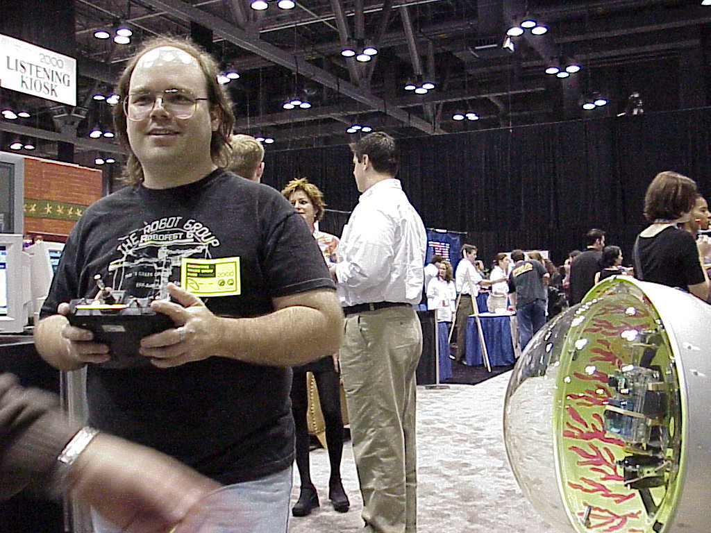
Commander Salamander

The Robot Group is extending its experience with indoor blimps to the great outdoors.

Using a surplus envelope for the Mark IV and adding hot model airplane competition motors spec’d by guru George Parks, plus a video link and possible GPS unit we could demonstrate many new mission capabilities. Tom Davidson is designing and implementing the spread spectrum over the horizon video/data link.

Wish list :

1) mini GPS w/ serial port. I ‘m callin’ Trimble right now.

2) Balloonet system enabling stratospheric missions.

Missions will include sports events, natural disaster scouting, and environmental monitoring.

The Captain Salamander name was derived from local biologist’s (Jim Collett) concept for a Barton Creek inspection blimp.

Progress report by David Santos May 1996.

Generic Intellectual Property Statement- Patents mostly pending. Designs protected by copyright. Free noncommercial personal and educational use encouraged.