Author: rutrohverlord
I am, by nature, a creature of the web. My daytime vision is excellent although I prefer to roam, far and wide, under the cover of darkness.
Nightcrawler, woodsmith, metalsmith, scientist / engineer.
South by Southwest Interactive Media Trade Show 2001
In March 2001, The Robot Group, Inc. set up shop at the SxSW Interactive Media Trade Show. The highlight of the show was a catapult built by a local high school that was used for lobbing t-shirts and other goodies to show attendees.
")
SXSW 2001 Load-in at venue (L-R : Eyebot, Tai Chi arm, Aaron Lundquist, Derek Bridges, Lauren Kopplin carrying Babbling Head)
SXSW 2001 Load-in at venue (L-R : Eyebot, Tai Chi arm, Aaron Lundquist, Derek Bridges, Lauren Kopplin carrying Babbling Head)
")
SXSW 2001 Load-up at the warehouse (L-R : Aaron Lundquist, Tom Morin, Derek Bridges, Eric Lundquist, Bill Craig)
SXSW 2001 Load-up at the warehouse (L-R : Aaron Lundquist, Tom Morin, Derek Bridges, Eric Lundquist, Bill Craig)
")
SXSW 2001 booth all set up (Babbling Head on table, over banner, Eyebot)
SXSW 2001 booth all set up (Babbling Head on table, over banner, Eyebot)
")
SXSW 2001 booth (L-R : Don Colbath, Brooks Coleman, catapult in foreground, GatorGirl in background)
SXSW 2001 booth (L-R : Don Colbath, Brooks Coleman, catapult in foreground, GatorGirl in background)

SXSW 2001 Target area for catapult. Anna Nedeau in the bright footwear, Tami Friedman at the far right.
SXSW 2001 Target area for catapult. Anna Nedeau in the bright footwear, Tami Friedman at the far right.

SXSW 2001 Radio-controlled Shop-Vac®
SXSW 2001 Radio-controlled Shop-Vac®

SXSW 2001 Brooks Coleman with mannequin
SXSW 2001 Brooks Coleman with mannequin

SXSW 2001 Eric Lundquist chats with attendees
SXSW 2001 Eric Lundquist chats with attendees. Babbling Head (on table) and Eyebot can also be seen.
")
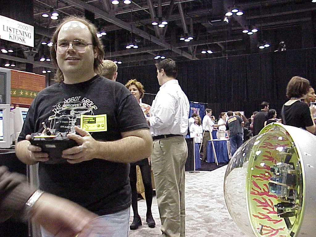
SXSW 2001 Eric Lundquist (with RC control unit)
SXSW 2001 Eric Lundquist (with RC control unit) steers Tom Davidson's & Sonia Santana's Eyebot around the floor.
Oscar, the Trash Can Robot
Oscar was created by Leon Hubby and Kevin Derichs
Oscar – he’s our own trash can man. He is made from a standard metal trash can and a servo controlled robot hand.
Oscar puts trash in its place. An object placed in the robot hand will trigger the mechanism to retract the hand into the trash can and dispose of it properly
Oscar could have been a great boon in the waste disposal industry. The kids at RoboFest certainly loved feeding him. When Oscar is around, floors remain pretty spotless.
[Images and text initially from http://www.robotgroup.org/projects/oscar.html]
Sparky, the Robot Pup
Tim Sheridan designed and built a radio-controlled (RC) servo “pup” capable of sitting, standing, walking, and barking. Alex Iles helped with the microcontroller implementation.
[]
PVC-frame Surveillance Robot
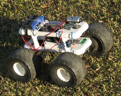
Bob Comer (and son, David) have been working on a surveillance robot with remote telepresence. The robot is constructed using a PVC frame and drive components (motor, gearbox, and wheels) scavenged from old kids’ electric ride-on toys.
The robot is equipped with
- Imagine Tools Ethernet Starter Kit – Rabbit 3000 microprocessor with web server. Source : www.jameco.com
- Robot Power Scorpion XL 2 channel speed controller. Source : www.robotmarketplace.com, www.robotpower.com
- Linksys WRT54G wireless router. Source : Best Buy, CompUSA, Frys, etc.
- Airlink AIC250 ethernet camera. Source : Frys, etc.
The robot is programmed in Dynamic C and has a web page as an interface. You can drive the robot from any computer with wireless networking and a web browser.
[Image and text originally from http://wiki.therobotgroup.org/wiki/RobertComer]
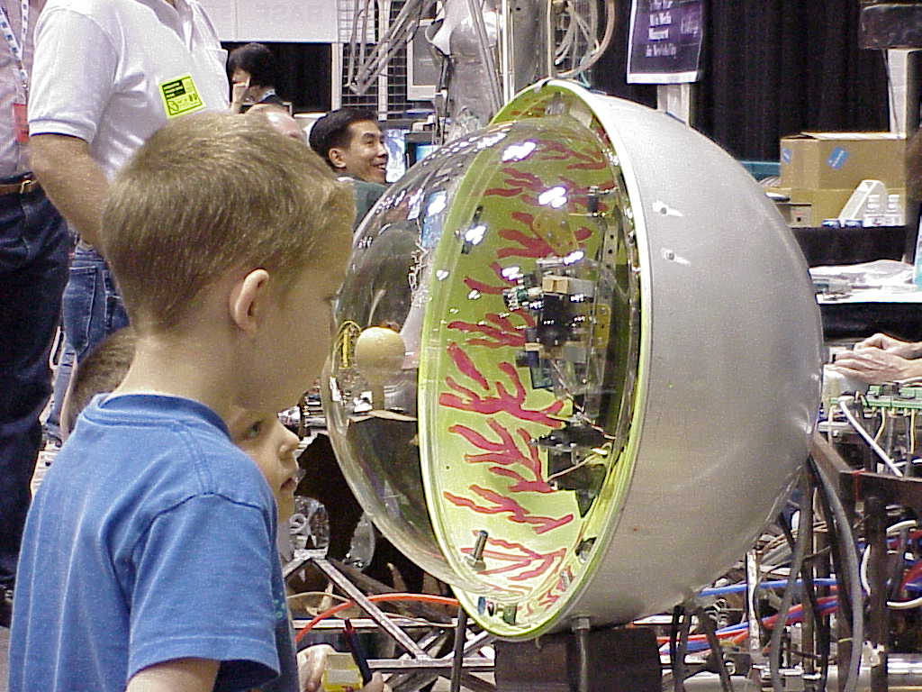
EyeBot
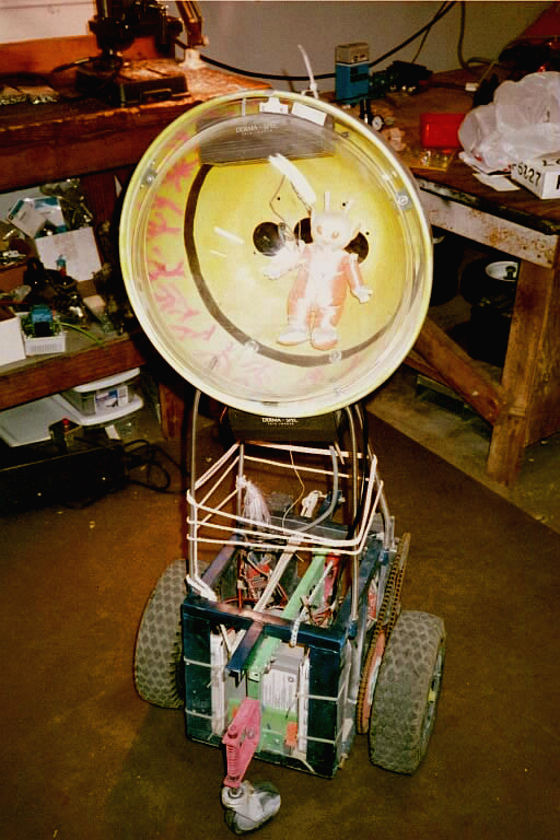
Tom Davidson & Sonia Santana are the forces behind, EyeBot, a mobile platform telepresence robot based on the Mobile Platform Mechanics. The control is a very basic R/C 4-channel using two 12V electronic speed controllers, and 2 R/C car servos.
The “Super-Rooster” speed controllers are capable of 128-levels of proportional control in forward and reverse and can handle up to 150 Amps at 12 Volts.
The servos are used in a gimbal which carries two Supercircuits microcameras, one an infrared monochrome camera and the other a high-resolution color camera. The video and audio signals are relayed by a X-10 2.4 GHz video transmitter-receiver pair.
Tom Davidson, co-creator of EyeBot @ SXSW 2000 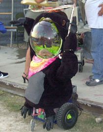
EyeBot as GorillaBot at CAM Carnival 2004 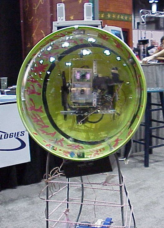
EyeBot @ SXSW 2000 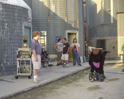
EyeBot as GorillaBot at CAM Carnival (San Antonio, TX) 2004-07-03 with Babbling Head, Tom Morin (standing), and Tom Davidson (seated)
EyeBot has made numerous appearances at The Robot Group events. The kids love EyeBot because it is approachable and appears to dance with them.
In addition, EyeBot appeared in the 2001 Robert Rodriguez film, Spy Kids.
SRL comes to ATX
Mark Pauline’s Survival Research Laboratories put on a show entitled “The Unexpected Destruction of Elaborately Engineered Artifacts : A misguided adventure in risk eradication, happening without known cause, in connection with events that are not necessarily related” at Longhorn Speedway, Austin, TX on 1997-03-28.
The SRL show was produced Bill Craig, Tom Davidson, and Paco X with substantial logistical assistance provided by Diana DeFrancesco.
For reasons of liability, The Robot Group, Inc. was not involved in any way with the production or the promotion of the show. Individual members were free to volunteer or help as they wished.
[Editorial note : I am awaiting Mark Pauline’s permission to use the Austin show’s poster as the featured image on this page.]
Mobile Robotic Platform
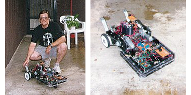
Eric Lundquist‘s Mobile Robotic Platform was an experimental built-from-scratch design with several unique features. Its behavior was very moth-like in that it chased the brightest light that it could detect. Obstacles were detected and avoided with feeler wires on 3 sides.
The brains of the Mobile Robotic Platform were a Parallax BASIC Stamp I providing 8 I/O lines and programming in a dialect of BASIC. Eric added a Stamp Extender that provided an additional 16 I/O lines.
The BASIC Stamp drove the motor and direction relays, the LEDs, and the Piezo buzzer. It also monitored the status of bumpers and polled light levels from its 3 photocell “eyes”.
The base was painted pine shelving material. Not only was this low cost, it did not require any specialized tools to work aside from a circular saw. It also made it exceptionally easy to mount, fasten, and rearrange things.
Eric’s ultimate goal with this project was to add several more BASIC Stamp controllers to make a distributed parallel architecture. This would have allowed more complex behavioral responses and interactions with the environment.
Negative Head
[Editor’s note : This information was extracted from an entry in an old version of The Robot Group web site archived by the Wayback Machine on 1996-12-04. Sorry, no photographs have emerged to-date.]
Negative Head is another face character for the planned robot theatre performance being directed by Brooks Coleman. The Negative Head is made from street lamp parts and servos. It creates face movements by overlaying transparent patterns to grids.
Arthur … The Door Butler
Leon Hubby proposed this project.
Description
“Arthur … The Door Butler will resemble a very normal door. As you approach, you will see a door mounted in a partial wall with a very standard motion detector mounted at the top and a porch light to the side. A welcome mat will greet the visitors.”
Operation
“As the visitors approach, the motion detector will turn on the porch light and enable the door to greet the individuals. When the visitors step on the welcome mat, Arthur will open and then close the door for them. First, a compartment on the side of the door will open, a robotic arm will unfold, raise itself, and position to grasp the door knob. Arthur will then grab the door knob, rotate it, and open the door. A mat on the other side of the door will signal Arthur that the individual has passed through. The arm will then close the door, release its grip, and refold itself up closing its access door. “
Artistic and Technological Content
“Art, as they say, is in the eye of the beholder. From my perspective the door represents a sculpture in motion. The image of an automatic door does not invoke much artistic impression. A door that lends a hand and opens itself, however, tends to be a bit more intriguing, if not novel. The technological content is centered around making a light-weight yet strong arm and gripper. This project will explore the use of different sensors to detect individuals, the door knob, etc. Differing techniques will be used to center the gripper on the door knob, close around the knob, and rotate to open it. This project will also explore the control aspects using the HC11E9. Special efforts and attention will be placed on the construction of the arm in order to build a light-weight, strong arm. The arm will be constructed of either PVC pipe or Styrofoam coated with epoxy fiberglass.”