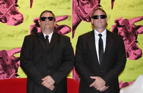
On Thursday, September 4th, 2003, at 7:00pm, the Austin Museum of Art (823 Congress Ave, Austin, 78701) presented “Another Fifteen Minutes : An Evening with Warholabot and Ediebot.” Admission was $5.00.
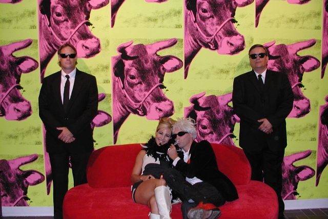
The show was in conjunction with the opening of AMOA’s new Andy Warhol exhibit. Robot Group members, the dashing Glenn Currie and the grizzled Eric Lundquist, portrayed the mysterious Men in Black.
“Andy Warhol once said that he wanted to be a machine. What if he actually became a machine?
In 2017, a mysterious group of beings, known as The Nine, have extracted Andy’s soul essence and inserted it into an Andy Warhol robot.”
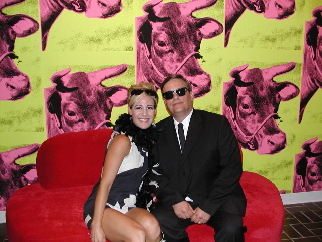
“Andy Warholabot and Ediebot (Warhol Superstar Edie Sedgwick) will time-travel from 2017 in an Interdimensional Limousine to 2003 in order to put in an appearance in the gallery of the AMOA where they will be interviewed by Mega 93.3 DJ Miss Kitty. Don’t miss this rare opportunity to hear Andy Warholabot and Ediebot talk about art, fame and silver pillows.”
Written and Directed by Sidney Moody
Robert Patterson as Andy Warholabot
Lisl Friday / Acclaim Talent as Ediebot
Miss Kitty playing herself as “The Interviewer”
Glenn Currie and Eric Lundquist as the Men In Black
Editor’s note : The contents of this page were extracted an archived entry found on the Internet Archive’s Wayback Machine. The page, originally on Carlos Puchol’s web space at The University of Texas – Austin, was archived on 1996-12-31.
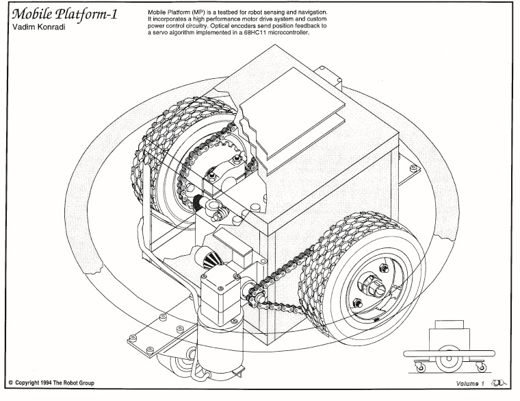
Introduction to the Mobile Platform
The mobile platform project is designed to provide ground-based mobility to experimental sensor and control systems, allowing them to traverse level surfaces such as building floors, and possibly streets and backyards. Think of it as a Hero robot on steroids.
Mobile Platform Mechanical System
The mobile platform is supported by two main drive wheels, with stability augmented by fore and aft caster wheels. Depending on distribution of weight in the platform and payload, it may be self-righting through balancing about the main wheel axis. Possible caster wheel heights are bounded on the low end by the need to negotiate unlevel surfaces and, on the high end, by the need to maintain the platform more or less level during dynamic maneuvers. Caster wheel mounting heights and possibilities for controllable height adjustments need to be investigated.
Vadim Konradi's Mobile Platform
Vadim Konradi's Mobile Platform
Vadim Konradi's Mobile Platform
Vadim Konradi's Mobile Platform
The vehicle platform is designed to fit within a 2-foot circle so it can navigate doorways and turn within its width. Currently equipped main wheels are 11.5 inches high. The platform structure is made up of 1-inch square steel tubing in a box structure. Vertical hard clearance when level is 2 inches. The top of the box structure is 12 inches above the floor. In general, platform structure below the 12 inch height is intended to be dedicated to platform mechanicals, and passenger equipment will mount to the top surface. The upper surface consists of a perimeter structure of 1-inch square tube, 10 inches wide by 11 inches fore-aft. We will equip it with mounting holes or tabs, or studs, or tape things on top with duct tape.
Platform main wheels are driven from wheelchair motors via #35 roller chain. Based on preliminary observations, motive force of the system will be limited primarily by tire friction. Based on measured motor torque of _____, and a _____ : _____ reduction ratio, the horizontal stall force will be _____. Thus a heavily-loaded platform will be able to push over or drive through certain static objects. Some motor current sensing or other safety mechanisms may be appropriate. A perimeter bumper system with contact switches will likely be installed eventually.
Mobile Platform Electrical / Electronic System
The mobile platform electronics are designed for control via a Motorola 68HC11 microcontroller Evaluation Board (EVB). The EVB receives movement commands from a higher authority and performs the necessary control functions to drive the platform motors. The EVB has been used as a basis because it is a handy development system. Eventually the motor drive circuit board will probably have an on-board HC11.
Control is currently passed to the EVB via a standard serial port for testing in conjunction with a data terminal. Eventually control will be migrated to the HC11 Serial Communications Interface (SCI) for interprocessor communication.
The motor drive power electronics reside on a circuit board with the same dimensions as the EVB and similarly placed 60-pin connector. It is capable of being mounted, with a suitable connector, as a daughter board on top of the EVB. Logic and motor drive circuitry are separate, with optical coupling of control and status signals in both directions. Motors are controlled via enable and direction signals. The enable is pulse width modulated (PWM) to control motor speed. In addition to the individual motor enables, a global driver enable allows shutdown of the entire power output stage. An overcurrent sense signal is sent back from the motor driver circuit to the HC11.
Each motor driver consists of four MOSFET transistors in an H-bridge configuration, controlled by a _____ IC. The most recent circuit version is equipped with IRF540 MOSFETS, giving it current capability of 27 A continuous, 108 A peak. This appears to be a reasonable transistor size for efficient operation at anticipated motor power levels. MOSFETS with higher current ratings may be substituted as required. The motor driver circuit is currently programmed for overcurrent limit of approximately 20 A, which may be modified by changing the current sense shunt.
Optical encoders on the motor output shafts are used to feed back motor position to the HC11. Each encoder consists of a pair of optical interrupters and an encoder wheel. The encoder sensors use a Schmitt trigger buffer to control encoder hysteresis. Optical encoder outputs are fed to the HC11 via connectors on the motor driver board. Connectors are 4-pin .100 type.
The motor driver circuit board is designed to operate with input voltage in the 5V-30V range. Full turn-on saturation of the MOSFETS is not guaranteed below 10V, so operation is not recommended in this range with a large motor load. Power connectors on the power board are Molex .093 series 2-pin connectors, connecting to male connectors on batteries and female connectors on motors. The motor drive circuit is fused with a standard automotive type fuse. The fuse should protect against melted wires and boiling batteries in the event of an output short. Current limiting by the transistor driver IC should protect the MOSFETs to some degree. This will no doubt be determined experimentally at some time.
There is an undesirable and potentially exciting design defect on the current version of the power board, resulting in runaway full-speed drive of the motors when power is removed from the control logic. This will be corrected on future versions. For the moment, it is necessary to ensure that logic power is applied prior to application of motor drive voltage, and motor drive voltage disconnected prior to disconnection of logic power.
Control Algorithm
General
The HC11 program which controls platform motion is mainly interrupt-driven. Encoder transitions are serviced as they occur. A real-time counter schedules updates of the trajectory generator and control loop. PWM transitions are controlled by HC11 internal timers, which are reset at the PWM frequency. Implementations of these functions are more or less similar to HC11 databook examples.
Movement Command Set
Platform movement is directed through commands to the HC11 via the serial port. The following is a summary of currently implemented commands :
Calibrate – sets setpoint position equal to current position (overrides move in progress)
Translate (direction,magnitude) – forward or reverse increment to current setpoint position
Rotate (direction, magnitude) – rotates right or left about platform centerline
Velocity (direction, magnitude) – gives platform velocity in specified direction
Radius (direction, length) – specifies curve radius in conjunction with velocity commands
Motor (direction, magnitude) – allows independent increments topology motor setpoints
Control (various parameters) – allows resetting of control equation constants and limit values
“Magnitude”, a parameter in many commands above, is expressed in terms of encoder counts, and the relation to physical movement distance is a function of encoder resolution, gear ratio, and wheel size. Encoders should eventually be sized such that some whole number relation exists between counts and distance in standard units of measure. Radius is specified in increments of half the vehicle track.
Commands as currently implemented return prompt strings to the data terminal. Such information will be omitted for interprocessor control via the SPI.
Wheel Position Settings and Trajectory Generation
Each wheel has an associated destination position counter. The count values are modified through addition and subtraction of increments for instantaneous movements. Velocity commands cause the velocity value to be added to the wheel counts at the trajectory generation timestep interval. When a non-straight path is directed via the Radius command, the destination counts are incremented differently to achieve the desired radius. Operation at large radii is not smooth; the algorithm may be modified someday.
Translation, rotation, and velocity commands may be overlaid with predictable, though not always intuitive, results. In general, translation and rotation commands are intended to be applied disjointly, and separately from velocity commands. Velocity and radius commands are intended to be used together in a smooth manner. All commands take effect immediately but translations and rotations modify endpoint positions, whereas velocity and radius commands modify the incremental setting of new endpoints.
Eventual additions to the command set may include profiled moves, consisting of acceleration, maintained velocity, and deceleration. Other means of limiting acceleration and jerk forces via programmable limits are possible. Another feature, primarily applicable to translation and rotation commands, would be the ability to queue commands, i.e. move forward 5, turn left 2, move forward 8. Eventually the command set will probably need to be divided into two or more distinct modes of operation.
Encoder Sensing and Actual Position Determination
Optical encoders send two digital signals in quadrature to HC11 inputs. Transitions on one signal are recognized, at which point an interrupt routine reads the other signal and determines direction of encoder motion. New position is compared with previous position for the possibility of encoder error which is not really handled correctly right now anyway. Then the wheel position count is incremented or decremented as appropriate.
Generation of Motor Force Function
Voltage applied to each motor is determined via a comparison between destination position and actual position. If there is any difference, the control algorithm exerts force through the motor to drive the error to zero. The position control is implemented in a proportional-integral-derivative (PID) loop, with command-settable gain values for each term. The motor PWM duty cycle is also subject to a command-settable limit. The result of the control calculation is a duty cycle, which is used by the PWM logic to generate a PWM output from the HC11 for the motor driver circuit.
Error / Failure / Problem Resolution
Some work needs to be done in recognizing problems with platform motion such as bumping into objects, motor overcurrent, encoder / drivetrain / wheel slip, etc., and acting on these problems accordingly. The control algorithm will need to shut down activities which are causing problems and report back to its higher authority.
Balancing Act
Since the platform has two wheels, fairly responsive motors, and a dedicated controller, it may be possible to perform active balancing of top-heavy loads without relying on the caster wheels. This is actually not that farfetched, but would require some attitude-sensing hardware and algorithm development. It would also be totally cool.
Glenn Currie’s design for the Mobile Platform (from TRG Coloring Book by Norm Annal 1994).
The Megabot robot series is a design for a muti-purpose utility robot. Project members, Norm Annal and Glenn Currie, developed a design similar to that of a toy robot, but on a much larger scale. The design specifications call for the robots to be made of plastic and dense foam. There will be different models and they will range in height from 8 to 24 feet tall. Sensors will provide an array of interesting sounds and dazzling light effects.
Megabot Proto 1
The Megabot Proto 1 was the first prototype of the Megabot series. It was constructed from recycled materials and off-the-shelf items. This robot demonstrates that robots can be built from very inexpensive materials like cardboard.
Let’s begin at the base. The oversized eet and legs are carved from corner strips of foam packing material using a razor blade. The leg pivot-points rotate on PVC tubing, and turn inside bushings made of plastic tubing cut into short lengths, which are then sunk into the foam lower limbs and lower torso. Cardboard from pizza boxes and shipping cartons were used to reinforce these leg and foot parts. The cardboard is attached to the foam pieces with glue and sturdy toothpicks.
The feet are modular and easily replaced . They are also constructed of foam but with are reinforced with a fiberglass coating. A cardboard-covered foam wheel is embedded in the rear of each foot. Each wheel rotates on PVC tubing which also connects the foot to the lower leg bone and the forward-lifting shin bone. A microswitch, inserted into the bottom of each foot, will be linked to a sound chip to produce mechanical sound and/or the activation of warning lights during foot movement.
The lower torso houses the motor and battery power for the robot’s movement. A battery operated socket wrench serves as the motor unit. A small bicycle gear, welded to a 1.12 diameter socket, turns a larger gear which then moves the offset rotating cam. The cam is constructed from PVC tubing. A small length of bicycle chain is also used. The gear box is currently constructed from layered and shaped cardboard which proved to be too weak and flexible to maintain the rigidity required to keep the gears apart. Stiffer cardboard or plastic-coated cardboard could solve this problem as well as the flexing of the PVC and compression of the foam.
The upper torso is made completely of cardboard and is easily removed and replaced with other upper torso designs. This robot is designed with a lot of modular components so that it can be easily changed.
The head piece is a plastic helmet filled with foam, a battery pack and small lights. It is mounted on a PVC tube for side-to-side rotation. The foam neck section pivoted forward and backward. All this weight proved to be too much for the motor and gear box in the Megabot Proto 1.
Plans were made to lighten the load for the second prototype.
Megabot Proto 2
For Megabot Proto 2 (MP2), the robot design went almost entirely to a cardboard-based unit. The legs and feet were constructed only of cardboard eliminating the heavier foam pieces. The cardboard material was cut and glued at right-angles to add strength to the design. The motor and gear box unit were removed from the MP1 for use in this second version. No major modifications were made in the original design for these pieces.
The upper torso again is completely cardboard. The hand and finger digits are carved foam with sturdy toothpicks for the pivot points. The digits can be manually positioned now but plans are to have them servo-controlled.
The head piece on the MP2 also went to the lighter cardboard version eliminating the plastic and foam from the first prototype. The MP2 head and arms are intended to be covered and eventually used for molds for mass production of the Megabot Army. Small servos could be adapted to move and control the head and arm pieces.
This version of the Megabot, the MP2, successfully walked for a brief period in a test work-session. The test walk proved that the design concept is good. Additional work is needed to replace parts where stronger materials are to be used, for example, in the gear box unit. In general, all the high-stress points on the robot should have stronger or plastic-coated cardboard.
The current robot shell on the MP2 is very impressive looking. The robot face appears to be an animal snout and the side profile shows pointed dog type ears on the head piece. The cardboard pieces were painted black and the eye socket areas are set back and painted red. The complete head piece gives the appearance of a space helmet for a robot dog.
The leg and lower torso units are also painted black while the upper torso unit is blue. The PVC pieces are painted red and the foam pieces on the hand were painted yellow.
Norm put over 1,000 hours of time into this project individually cutting and molding each of the pieces for the two units. In addition, he did the design illustrations for the project. Glenn also assisted in the design and work.
The Megabot Army was an attempt to build a 6 foot tall robot out of regular cardboard that you would assemble by folding (akin to the manner in which you would assemble a cardboard file-storage box).
“When we give demos at schools, the kids always ask about a robot kit. Robots get expensive very quickly.”
Glenn Currie
Norm Annal did much of the design which was fed into AutoCAD. The output file was used to drive a CNC prototype box-cutter at Capitol Container in Buda TX just south of Austin. Capitol Container cut about a dozen of the robot kits for us and several have been assembled and used in various displays.
The nice thing about having the drawings in AutoCAD is that we can adjust the size easily. One 3 foot tall version of the Megabot was built. I need help on this project. It has been in the attic since Robofest 7. Many thanks to Capitol Container – those folks can make anything out of cardboard.
Dweebvision, a low cost video telepresence rover, is one of Glenn Currie‘s creations. A durable as it is simple, Dweebvision has survived operation by hundreds of kids over five RoboFests and many school events.
The Dweebvision vehicle is a radio controlled toy car, equipped with Pixelvision video camera and transmitter.
The chassis is made out of an “after Christmas” special 4-wheel drive truck from Radio Shack. The remote control for steering the base is on ~27 MHz. and offers no interference for the 900 MHz. audio-video transmitter. The unit runs for about 4 1/2 hours on one set of alkaline batteries. I added a xenon strobe to Dweeb for safety because all kids want to do with it is drive up behind someone and have them trip over the robot.
The person at the control station sees and hears the world in Dweebvision, and can control the car as it navigates its surroundings by viewing a monitor. Many of the children visiting RoboFest watched in amazement as no one seemed to be controlling the RC car. The navigator can sit out-of-sight from the vehicle and have a little fun teasing the kids.
“I built the group’s first telepresence bot called Dweebvision. It has (yes, it is still working) a Fisher Price Pixelvison camera attached to a 900MHz. audio / video transmitter. Dweeb sends back live video and sound. The automatic audio gain control in the Pixelvison camera works perfectly – reducing the audio while the unit is driving around and the noisy plastic gear motors are on and increases the microphone sensitivity when the motor noise stops.”
Glenn Currie
Dweebvision was built, overnight, before Robofest III, after collecting all the parts over the period of a few months. It gets updated, at times, with a night vision camera and has been used to scout out problems under an ice rink and look for pets under houses. Dweeb is a telepresence device and is run by a remote operator. It has no on-board microprocessor or brain. When I was in school we called a person with no apparent brain and a head filled only with that which was put there by others, a “Dweeb”.
“Dweeb has been used in countless demonstrations over the years. I found attaching the camera and video transmitter with rubber bands and Velcro was the way to go. Anything less flexible was trashed in no time. With rubber bands and Velcro I simply pick up the “big chunks” of the robot after it has been stepped on and mash them back into place. Most schools have walls of enameled brick and Dweeb gives a great demo when driven between desk legs in nearby classrooms. Dweeb is small and travels in a cardboard file box to school demos.”
Glenn Currie
Dweebvision was the first of the telepresence robots created by Robot Group members. The Mobile Platform followed soon afterwards.